 The Boy Scouts is unquestionably the best youth program that exists. If you would like to learn more or find a local troop to join, go to the BSA website. I’ve been a Scout leader for many years and will be glad to also assist with any questions you may have.

Tuesday, August 30, 2011
Congrats to my new Eagle Scout!
This post isn’t about software or sawdust but about something more important. My son was awarded the highest rank in Boy Scouts this weekend – Eagle Scout. Only about 2 out of 100 boys that start the Scouting program achieve this and I’m very proud of him. He’s worked very hard (with a lot of encouragement ;). I’m sure this is going to be the first of many great accomplishments we see from him.
 The Boy Scouts is unquestionably the best youth program that exists. If you would like to learn more or find a local troop to join, go to the BSA website. I’ve been a Scout leader for many years and will be glad to also assist with any questions you may have.


Wednesday, August 24, 2011
Omnicopter–Power Wiring Harness
Lately, I’ve been working on the power distribution (wiring) harness for the Omnicopter. This turned out to be a much bigger challenge than I had anticipated. My design objectives for the Omnicopter dictate that I must eventually be able to support.
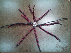 Although I am currently only using four motors and one battery, I knew this was one part of the project that would be a lot easier to only do once. Also, because of my electrical current requirements I decided to use 12 gauge wire which is thicker and less flexible than the smaller gauge wires. Getting all the wire in my 1/2” thick frame proved to be a bit of a challenge.
My first attempt was to try splicing all the different wires together by soldering two or three wires together at a time then covering with shrink tube. This proved to be an impossible task. Soldering this thick of wire together like this is very difficult and because of all the joints and shrink tube it simply wasn’t going to fit into the frame if I did get it all soldered together.
 So, after researching and doing a lot of thinking I decided on what I believe is going to be an excellent design. I found an example on the net that served as inspiration where he twisted the ends of the wires together into a loop. That seemed it would be a bit difficult to solder and then you would also have to add an insulator between the positive and negative rings which would add bulk. I finally got the idea that a ring of double-sided PCB would serve the purpose marvelously.
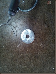 Using a whole saw, I cut out a 1” circle of the PCB. Because I wanted to be able to run a wire up the center to feed the microprocessor, I then drilled a 1/2” hole in the center. After washing and roughing up with some fine sandpaper on both sides of the board, I then put a heavy tin of solder on both sides to help thicken the metal and allow it to handle the higher current and to ease in soldering the wires. Next, I spent most of the afternoon soldering… After this was all completed, I ran across an article that pointed out that making a closed loop like I did risks the possibility of creating inductance which may later cause me problems. If I had it to do all over again, I would have removed a thin slice from each side of the PCB to break the loop. But, once the copper is tinned and the liquid tape is on it's a bit more hassle to do. So, I'll keep this in mind if any problems should arrise that I think may be due to this. If I were starting over, I would have definitely put this into the original design.
 Once all the wires were connected to the PCB loop, I soldered on all of the XT60 connectors. I used female yellow plugs for the motor connections and male plugs for the battery connections. Using a red Sharpie, I colored the battery connections also for easier identification.
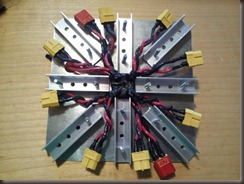 The battery wires were run in parallel and leads were run to the outside of the frame to allow for a switch to be connected between the batteries and the rest of the harness.
 Once all the soldering was complete, I painted on plenty of liquid electrical tape on all the exposed metal surfaces including the entire PCB ring.
Then I used my meter to test for any shorts (probably should have done this before the liquid tape). Thankfully, everything tested perfect. So, I put the top side of the frame on and tightened her back down.
Now I have to solder up the ESCs to the motors and the matching XT60 connectors then it’ll be time to start the fun work of figuring out how to make it fly.
- 8 x 30amp brushless motors
- 2 x 3-cell Li-Po batteries
 Although I am currently only using four motors and one battery, I knew this was one part of the project that would be a lot easier to only do once. Also, because of my electrical current requirements I decided to use 12 gauge wire which is thicker and less flexible than the smaller gauge wires. Getting all the wire in my 1/2” thick frame proved to be a bit of a challenge.
My first attempt was to try splicing all the different wires together by soldering two or three wires together at a time then covering with shrink tube. This proved to be an impossible task. Soldering this thick of wire together like this is very difficult and because of all the joints and shrink tube it simply wasn’t going to fit into the frame if I did get it all soldered together.
 So, after researching and doing a lot of thinking I decided on what I believe is going to be an excellent design. I found an example on the net that served as inspiration where he twisted the ends of the wires together into a loop. That seemed it would be a bit difficult to solder and then you would also have to add an insulator between the positive and negative rings which would add bulk. I finally got the idea that a ring of double-sided PCB would serve the purpose marvelously.
 Using a whole saw, I cut out a 1” circle of the PCB. Because I wanted to be able to run a wire up the center to feed the microprocessor, I then drilled a 1/2” hole in the center. After washing and roughing up with some fine sandpaper on both sides of the board, I then put a heavy tin of solder on both sides to help thicken the metal and allow it to handle the higher current and to ease in soldering the wires. Next, I spent most of the afternoon soldering… After this was all completed, I ran across an article that pointed out that making a closed loop like I did risks the possibility of creating inductance which may later cause me problems. If I had it to do all over again, I would have removed a thin slice from each side of the PCB to break the loop. But, once the copper is tinned and the liquid tape is on it's a bit more hassle to do. So, I'll keep this in mind if any problems should arrise that I think may be due to this. If I were starting over, I would have definitely put this into the original design.
 Once all the wires were connected to the PCB loop, I soldered on all of the XT60 connectors. I used female yellow plugs for the motor connections and male plugs for the battery connections. Using a red Sharpie, I colored the battery connections also for easier identification.
 The battery wires were run in parallel and leads were run to the outside of the frame to allow for a switch to be connected between the batteries and the rest of the harness.
 Once all the soldering was complete, I painted on plenty of liquid electrical tape on all the exposed metal surfaces including the entire PCB ring.
Then I used my meter to test for any shorts (probably should have done this before the liquid tape). Thankfully, everything tested perfect. So, I put the top side of the frame on and tightened her back down.
Now I have to solder up the ESCs to the motors and the matching XT60 connectors then it’ll be time to start the fun work of figuring out how to make it fly.
Monday, August 15, 2011
Omnicopter – The Frame is Built

 The princess is not happy… The frame for the Omnicopter is built and the motors are installed but it doesn’t fly!!! Women. They want everything “right now!”. ;) However, I later wired up one of the motors and put a prop on it and showed her what’s coming. She’s quite pleased at that. I’ll admit that I was also. I built this frame as more of a lab/test frame than a final version. It has a lot of flexibility built into it as far as arm placement goes and very little attention was taken to try and reduce weight. With 20% power given to one motor with a prop it produced enough lift to lift half of the frame and motors off the ground. Once all four motors are up and running it will have more than enough power to lift itself and probably 2-4 additional pounds. Can’t wait to have that test!

I’ll post some additional detail about the frame later. Now to build the wiring harness…
Saturday, August 13, 2011
Using an External Button & LED with NETMF
In continuing with the 
Nearly every NETMF basic tutorial out there starts with a very simple program that uses the on-board button to light up the on-board LED. That’s just great and is absolutely fantastic the first time you write a NETMF program. However, as soon as you start working on a real project you soon discover that the on-board button & LED have very limited uses since they can’t be exposed outside of your project enclosure. Then the question comes up – how do I add more buttons? How do I light up an LED on my project box? How do I use more than one button or LED?
I’m going to demonstrate how to do this in the most basic situation – the one that will work for 95% of all hobbyist’s needs.

For this project, you’ll need a momentary button, an LED, a breadboard, one 10K ohm resistor, one 100 ohm resistor, and some wires.
Like most things, there are many ways you could wire this up. This is just one. What I did was to first plug my button into the breadboard and wire one side of the button to the ground line (very top row on the breadboard). Then, I connected a 10K ohm resistor (brown, black, orange) to the power (5V) line (2nd row on the breadboard) and used it to connect power to the other side of the button. The 10K resistor prevents us from creating a “short” which could fry the electronics by allowing too much current to be pulled through the electronics. Next, we put a 100 ohm resistor (brown, black, brown) on the power side of the button then connect the other side of the resistor to the analog 0 pin on the Panda-II. This resistor prevents too much current from getting into the board and damaging it.

Now that we have the button wired up, we’ll wire up the LED. Since only a very small amount of current flows through pins of the Panda-II board we can connect the anode/positive side (longer wire) of the LED to the D5/PWM5 pin and wire the cathode/negative (shorter) side of the LED to our ground line. That’s it for the wiring.
I do want to note here that if we were wiring the LED to an external power source that we would need to add a current limiting resistor to one side. To determine the correct size resistor, you can use an LED calculator.
Now that we have the hardware all wired up, it’s time to write some software that responds to our button being pressed by lighting the LED.
In Visual Studio, we create a new console project and add the following references:
FEZPanda_II_GHIElectronics.NETMF.FEZ
Microsoft.SPOT.Hardware
Microsoft.SPOT.Native
mscorlib
In our Program.cs file that is automatically created, replace what is there by default with the following.
using System;using System.Threading;using Microsoft.SPOT;using Microsoft.SPOT.Hardware;using GHIElectronics.NETMF.FEZ;namespace ExternalButtonAndLedTutorial{public class Program
{ // Tell the CPU we're going to use digital pin #5 to send a signal to the LED.static readonly OutputPort _led = new OutputPort((Cpu.Pin)FEZ_Pin.Digital.Di5, false);
public static void Main()
{ // Tell the CPU we're going to receive an analog signal from analog pin #0.var blueButton = new InterruptPort((Cpu.Pin)FEZ_Pin.Interrupt.An0, true, Port.ResistorMode.PullUp, Port.InterruptMode.InterruptEdgeLow);
// The second parameter in the line above ("true") tells the CPU that we want to use the "glitch" filter. // If you disable this line then run the program, you will notice in the debug windows that if you are not very fast // at pushing the button that the event will actually get fired multiple times. We only want the event to fire once. GHI gives // us this property that we can set to put a boundary around our first event and prevent redundant events from being fired. // Adjust the number of tickCpu.GlitchFilterTime = new TimeSpan(TimeSpan.TicksPerSecond/2); // 1 Tick = 100 nanoseconds
// When the button is pushed it will signal an interrupt in the CPU which will in turn cause an OnInterrupt event to be thrown. // Our BlueButton_OnInterrup function will be called when the interrupt/event is fired.blueButton.OnInterrupt += BlueButton_OnInterrupt;
while(true) Thread.Sleep(10);
}
private static void BlueButton_OnInterrupt(uint port, uint state, DateTime time)
{_led.Write(true); // Turn on the LED
Thread.Sleep(1000); // wait 1 second..._led.Write(false); // Turn off the LED
Debug.Print("Blue Button Pushed! " + DateTime.Now.ToString());}
}
}
I’ve chosen to document the code as comments in-line, but if anything isn’t clear please leave a comment and I’ll clear it up.
Make sure and set your project properties to deploy to the USBizi device then run it. If you’ve done everything correct then when you push the button the LED should come on for half a second then turn back off.
Now that you have one button and one LED working, get creative! You can reproduce this many times and as many different ways as your imagination will allow. To use more buttons or more LEDs, just use any of the other pins and be sure to specify in your code when you define your buttons or LEDs which pin they are connected to and you’ll be fine. Put these new skilz to work and be sure to post your results in the comments!
NETMF for Electronics Noobs Tutorials

Although in most of my tutorials, I will use the GHI Panda-II microprocessor board the techniques can directly be applied to netduino or most any other NETMF device with minor code changes.
I’ll update the following list of topics as I add posts (I’ll try to add one weekly). So, bookmark this page and follow my blog if you want to keep up. If you have any specific topics you would like to see covered, please feel free to email me at ian (at) houseoflees.net or post to the comments below.
TUTORIALS:
- Basic XBee Communications with NETMF
- Using an External Button & LED with NETMF
- Controlling a Brushless Motor with NETMF
- Using a Joystick with NETMF and the NETMFx Joystick Library
FURTHER DISCUSSION
- TinyCLR.com – great place to ask questions regarding anything about the GHI Panda-II microprocessor and NETMF.
- netduino.com – great place to ask questions about the netduino microprocessor and NETMF.
- netmf.com – the official NETMF community forum
- Beginner’s Guide to .NET Micro Framework by GHI
- Getting Started with NETMF by Microsoft
- .NET & The Internet of Things by GHI (free eBook)
Monday, August 8, 2011
Basic XBee on NETMF
As I wait for parts for the Omnicopter, one of the things I’m getting started is the XBee radio communications between the remote/computer and the copter. My initial design will attempt to use XBee radios for all control of the copter as well as in sharing diagnostic & control data between the base station [remote & or PC] and the copter. I fear that XBee may end up not being responsive enough and have enough throughput to accomplish all things but that’s where I’m going to start before attempting traditional R/C radio techniques.
 I want to be able to control the Omnicopter both by a remote control I’m building based on a NETMF microcontroller and with software on a PC. The most basic of things is to make sure that the NETMF microcontroller I’ve chosen for the copter, a GHI FEZ Panda-II, can communicate with my PC.
For the Panda-II I have bought and assembled an Adafruit Protoshield and an Adafruit XBee Adapter. I already have some XBee Modules (series 1) from a previous project. So, I’m using them for now. Once I’ve proven the copter can fly and I’m brave enough to push the range limits of the XBee series 1 (300 ft.) then I can simply buy new XBee Pro radios and drop them in place of the existing radios to get a range of 6-15 miles (line of sight).
To test communications, two things are required – an XBee connected to the PC and a NETMF microprocessor with an XBee and the necessary software on both sides.
Setting Up An XBee on NETMF
An XBee radio communicates using basic RS232 type of communications. All that’s required to connect it to the Panda-II is to give it 5V power, ground, and transmit & receive signals.

For a better view of the wiring connections, I drew it up in Fritzing.
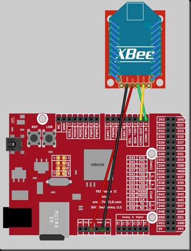
Note that the receiver (RX) on the XBee is connected to the transmitter (TX) on the Panda-II and vice-versa. This may not be obvious to those first getting started.
Next, we’ll need a NETMF C# program to install on the Panda-II. Visual Studio 2010 (VS2010) Express or better can be used to compile and deploy the program. GHI has a great tutorial on getting started if this is your first time to create a NETMF program. So, I’ll jump straight to the code. I’m using the MFToolkit open source code by Michael Schwartz to simplify the code required considerably. An alternative assembly that is somewhat easier to understand and seems to satisfy basic XBee needs is Grommet. Since I expect this project to get much more sophisticated over time, I’ve decided to stick with the MFToolkit.
Once you download the MFToolkit (or Grommet) code from Codeplex and create a new NETMF C# project, you can simply copy this code into your project to have the NETMF device send a “ping” every 5 seconds. The ping is basically the word “Hello” plus the current time in Ticks. The following code is not meant to be “production ready”. It’s just enough to test that the XBee is working.
At this point you should be able to compile and run your code from the Panda-II without issue and it will start sending it’s “ping”. Also, although I am using the Panda-II for this post just about any Arduino shield compatible NETMF device such as the netduino should also work w/o any change to the code or wiring.
Setting Up An XBee on a PC
Setting up an XBee on a PC is a bit simpler since all we really have to do is connect the XBee to a breakout or dev board with a USB cable and install the X-CTU software by Digi. No reason to write our own code for this test since there already exists this great utility that does everything we need to test & configure an XBee. I am using Windows 7 Ultimate (x64) but the steps are basically the same for any OS.

I have a MaxStream (now Digi) XBIB-U-Dev (Rev 3) XBee development board from a previous project that I’m using, but you can use just about any XBee adapter including the one from Adafruit that we used on the NETMF. On my board, I’m able to plug a USB cable directly into it. On most of the basic adapters, you will need an FTDI cable to convert the serial communications to USB. You will also need to locate and install the appropriate drivers for your OS.
 Once you have your hardware all figured out, we need to download and install the X-CTU software.
After you install X-CTU, run it and it should come up with something similar to this except the Baud setting will probably be at 9600. Set the baud rate to match that of your modem and hit the “Test/Query” button to see if X-CTU can connect to your XBee radio. Assuming you can connect and all is good then we’ll now see if we are receiving the “ping” from our NETMF device. Click on the “Terminal” tab and wait 5 seconds. You should see some text appear in red on the screen and more to be added every 5 seconds.
If we have this then we know we are properly sending from the NETMF device and receiving by the PC. Next thing to test is that we can send from the PC and receive from the NETMF device.
First make sure that we are running our program on the NETMF device through the VS2010 debugger and not just on the board itself. You’ll notice on our NETMF code that we are capturing XBee received data with the XBeeDataReceived() handler function. Anytime data is received, it will be simply printed to the Output Window.
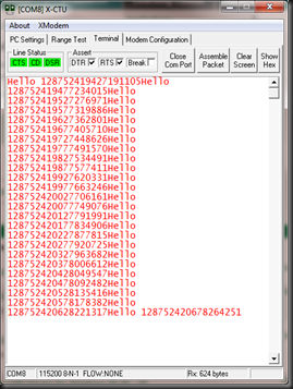 To send a packet of data from the PC we hit the “Assemble Packet” button in the X-CTU Terminal screen. We’ll send a simple “Hello World” packet. Type that in the textbox and hit “Send Data”. You should see “Hello World” printed in blue text in the X-CTU console and in the VS2010 output window you should see the same text also printed there.
Mission accomplished. We have established the most basic of communications and know that all of our hardware is setup properly and is working. Now the challenge is for you to figure out how to best utilize this power in your project by designing the data you will send and how to handle it properly when it is received.
If you are still having issues with hardware or software, you should start by checking the forums at any of the following sites.
 I want to be able to control the Omnicopter both by a remote control I’m building based on a NETMF microcontroller and with software on a PC. The most basic of things is to make sure that the NETMF microcontroller I’ve chosen for the copter, a GHI FEZ Panda-II, can communicate with my PC.
For the Panda-II I have bought and assembled an Adafruit Protoshield and an Adafruit XBee Adapter. I already have some XBee Modules (series 1) from a previous project. So, I’m using them for now. Once I’ve proven the copter can fly and I’m brave enough to push the range limits of the XBee series 1 (300 ft.) then I can simply buy new XBee Pro radios and drop them in place of the existing radios to get a range of 6-15 miles (line of sight).
To test communications, two things are required – an XBee connected to the PC and a NETMF microprocessor with an XBee and the necessary software on both sides.
Setting Up An XBee on NETMF
An XBee radio communicates using basic RS232 type of communications. All that’s required to connect it to the Panda-II is to give it 5V power, ground, and transmit & receive signals.

For a better view of the wiring connections, I drew it up in Fritzing.

Note that the receiver (RX) on the XBee is connected to the transmitter (TX) on the Panda-II and vice-versa. This may not be obvious to those first getting started.
Next, we’ll need a NETMF C# program to install on the Panda-II. Visual Studio 2010 (VS2010) Express or better can be used to compile and deploy the program. GHI has a great tutorial on getting started if this is your first time to create a NETMF program. So, I’ll jump straight to the code. I’m using the MFToolkit open source code by Michael Schwartz to simplify the code required considerably. An alternative assembly that is somewhat easier to understand and seems to satisfy basic XBee needs is Grommet. Since I expect this project to get much more sophisticated over time, I’ve decided to stick with the MFToolkit.
Once you download the MFToolkit (or Grommet) code from Codeplex and create a new NETMF C# project, you can simply copy this code into your project to have the NETMF device send a “ping” every 5 seconds. The ping is basically the word “Hello” plus the current time in Ticks. The following code is not meant to be “production ready”. It’s just enough to test that the XBee is working.
public static void Main()
{
    var ledBlinkerThread = new Thread(BlinkOnboardLed);
    ledBlinkerThread.Start();

    var pingThread = new Thread(SendPingWithMFToolkit);
    pingThread.Start();
}

private static void SendPingWithMFToolkit()
{
    var xbee = new SerialPort("COM1", 115200, Parity.None, 8, StopBits.One);
    xbee.Open();
    xbee.DataReceived += XBeeDataReceived;

    while (true)
    {
        string output = "Hello " + DateTime.Now.Ticks;
        byte[] bytes = System.Text.Encoding.UTF8.GetBytes(output);
        xbee.Write(bytes, 0, bytes.Length);
        xbee.Flush();
        Thread.Sleep(5000);
    }
}

static void XBeeDataReceived(object sender, SerialDataReceivedEventArgs e)
{
    int bytesReceived = ((SerialPort)sender).BytesToRead;
    var bytes = new byte[bytesReceived];
    ((SerialPort)sender).Read(bytes, 0, bytes.Length);
    var received = new string(System.Text.Encoding.UTF8.GetChars(bytes));
    Debug.Print(received);
}
Note that the second parameter of the SerialPort constructor in SendPingWithMFToolkit() specifies the baud rate of the XBee radio. By default, the radios will be set to 9600. I have changed mine to 115200 prior to this writing. If this is your first attempt with XBee then you should change this parameter to 9600 or whatever your actual baud rate is if yours have been changed to something different. The important thing to know is that both radios must be set to the same baud rate and the software on both sides is configured likewise.At this point you should be able to compile and run your code from the Panda-II without issue and it will start sending it’s “ping”. Also, although I am using the Panda-II for this post just about any Arduino shield compatible NETMF device such as the netduino should also work w/o any change to the code or wiring.
Setting Up An XBee on a PC
Setting up an XBee on a PC is a bit simpler since all we really have to do is connect the XBee to a breakout or dev board with a USB cable and install the X-CTU software by Digi. No reason to write our own code for this test since there already exists this great utility that does everything we need to test & configure an XBee. I am using Windows 7 Ultimate (x64) but the steps are basically the same for any OS.

I have a MaxStream (now Digi) XBIB-U-Dev (Rev 3) XBee development board from a previous project that I’m using, but you can use just about any XBee adapter including the one from Adafruit that we used on the NETMF. On my board, I’m able to plug a USB cable directly into it. On most of the basic adapters, you will need an FTDI cable to convert the serial communications to USB. You will also need to locate and install the appropriate drivers for your OS.
 Once you have your hardware all figured out, we need to download and install the X-CTU software.
After you install X-CTU, run it and it should come up with something similar to this except the Baud setting will probably be at 9600. Set the baud rate to match that of your modem and hit the “Test/Query” button to see if X-CTU can connect to your XBee radio. Assuming you can connect and all is good then we’ll now see if we are receiving the “ping” from our NETMF device. Click on the “Terminal” tab and wait 5 seconds. You should see some text appear in red on the screen and more to be added every 5 seconds.
If we have this then we know we are properly sending from the NETMF device and receiving by the PC. Next thing to test is that we can send from the PC and receive from the NETMF device.
First make sure that we are running our program on the NETMF device through the VS2010 debugger and not just on the board itself. You’ll notice on our NETMF code that we are capturing XBee received data with the XBeeDataReceived() handler function. Anytime data is received, it will be simply printed to the Output Window.
 To send a packet of data from the PC we hit the “Assemble Packet” button in the X-CTU Terminal screen. We’ll send a simple “Hello World” packet. Type that in the textbox and hit “Send Data”. You should see “Hello World” printed in blue text in the X-CTU console and in the VS2010 output window you should see the same text also printed there.
Mission accomplished. We have established the most basic of communications and know that all of our hardware is setup properly and is working. Now the challenge is for you to figure out how to best utilize this power in your project by designing the data you will send and how to handle it properly when it is received.
If you are still having issues with hardware or software, you should start by checking the forums at any of the following sites.
- GHI’s NETMF site: tinyclr.com
- Adafruit Forums
- SparkFun Forums
- netduino Forums
Sunday, August 7, 2011
Omnicopter - Getting Off The Ground
So, I've decided to start up another .NET Micro Framework (NETMF) challenge after taking almost two years off from the tiny framework. Some things have changed since I last used NETMF and I'm having to re-learn some things. Sadly, one thing that hasn't changed so much is the lack of abundance of documentation on some of the basic things required to get some very basic electronics goals achieved with the framework. So, as I start on this next project I plan to document some of the things that are either not already documented well somewhere else.
Unlike many NETMF developers I do not have a degree in electrical engineering. I'm a software guy. In all disclosure, I did spend three years studying EE at TTU before deciding to change to computer science so I do have a little more understanding of electronics than your average bear but I've never practiced it professionally and a lot of the language used in the NETMF forums and literature is a bit alien to me. So, as I work through this project and figure some of these things out I'm going to try and explain them as simply as possible to others such as myself. I believe the popularity of NETMF is only going to grow and one of the biggest set of new users is going to be software developers similar to myself and young roboticists. Both groups I believe will benefit.
 So, a brief intro to the project that I've decided to tackle. I'm going to build a multi-propeller helicopter (i.e. quadcopter, quadrotor, hexacopter, octocopter, etc.) In the first stages, it will start out as a quadcopter but I plan for that to change as progress is made. More about that when the time comes. Why build a quadcopter? Uh...they're really cool! But beyond basic flight, I have a lot of AI related ideas that I want to work on and the copter will be a great platform for developing those applications. Equally important is that there really doesn't exist yet a quadcopter built on NETMF that I'm aware. It seems that most people shy away or give up quickly because NETMF isn't a "real-time" platform and that it can't send commands quick enough to enable stability of a copter. I hope to prove them wrong. Maybe they'll prove me wrong but I don't think so. If they do then I'll be sure to document in painful detail why NETMF isn't a valid platform for copters.
I don't want to give up too much too soon on my plans for the project since I don't even know for sure that it will ever even leave the ground. So, for now there are two parts to this project:

Unlike many NETMF developers I do not have a degree in electrical engineering. I'm a software guy. In all disclosure, I did spend three years studying EE at TTU before deciding to change to computer science so I do have a little more understanding of electronics than your average bear but I've never practiced it professionally and a lot of the language used in the NETMF forums and literature is a bit alien to me. So, as I work through this project and figure some of these things out I'm going to try and explain them as simply as possible to others such as myself. I believe the popularity of NETMF is only going to grow and one of the biggest set of new users is going to be software developers similar to myself and young roboticists. Both groups I believe will benefit.
So, a brief intro to the project that I've decided to tackle. I'm going to build a multi-propeller helicopter (i.e. quadcopter, quadrotor, hexacopter, octocopter, etc.) In the first stages, it will start out as a quadcopter but I plan for that to change as progress is made. More about that when the time comes. Why build a quadcopter? Uh...they're really cool! But beyond basic flight, I have a lot of AI related ideas that I want to work on and the copter will be a great platform for developing those applications. Equally important is that there really doesn't exist yet a quadcopter built on NETMF that I'm aware. It seems that most people shy away or give up quickly because NETMF isn't a "real-time" platform and that it can't send commands quick enough to enable stability of a copter. I hope to prove them wrong. Maybe they'll prove me wrong but I don't think so. If they do then I'll be sure to document in painful detail why NETMF isn't a valid platform for copters.I don't want to give up too much too soon on my plans for the project since I don't even know for sure that it will ever even leave the ground. So, for now there are two parts to this project:
- Build a NETMF controlled quadcopter
- Build a NETMF based remote control.
I've decided to name my copter the Omnicopter - the copter with many propellers and many functions.

Unfortunately, it seems the only place you can really get the copter motors and other R/C parts is from Hong Kong (HobbyKing.com). So, there is a 4-6 week wait for parts. Ugg. I've ordered the motors and other R/C parts and they're on their way. While I wait for them to arrive, I'm doing some basic things with parts I can either acquire locally or order from the U.S. that arrive in a few days. I'm building the basic frame for the copter & figuring out some basic wireless communications and protocols that I want to use and playing with LEDs when I get tired of doing the real work. I'll cover all these things in future blog posts. Let's go have some fun!
Subscribe to:
Posts (Atom)