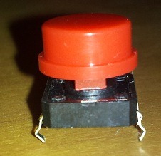
 Momentary buttons are probably one of the most common components in most projects. Unfortunately, most buttons are not made to be inserted into a breadboard. Most do line up and some will work if you are very nice to them. However, the pins are normally curved and very short so their ability to connect with the breadboard is very marginal and can lead to problems that may at first seem like issues with your microcontroller or the button itself. More than likely the issue is really just that the button isn’t making good contact with the circuit.
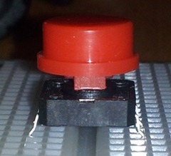 To eliminate this problem from my projects, I use the following process to make the buttons breadboard friendly. I recommend keeping a set of these specifically for breadboarding to save you time down the road. However, if you need to you can certainly reverse these modification later to use the buttons in your final product.
Basically, what I do is attach extensions to the “pins” coming from the button so that they fit tighter and deeper into the breadboard. This is certainly not an original idea. Many before me have done the same. However, since I was making up several of these recently I decided it would be good to document and reference later for others getting started in electronics.
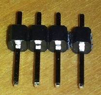 I start by getting a piece of male pin headers – one for each pin on the button. Hold the plastic housing with your fingers or a pair of pliers and then using some needle nose pliers, pull the pins out of the plastic. These pins are much more rigid than just wire and are easier to insert into the breadboard without worrying about them bending.
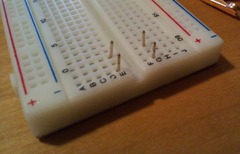 Once you have the pins out, find the holes on a spare breadboard that align with the pins of your button and insert the new header pins into these holes. Only push them in far enough that they are secure and try to make sure they are all sticking up the same height. We use this technique to ensure that when we solder the pins to our button that they will line up perfectly with the breadboard.
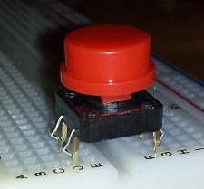 Next, we will place the button on top of the standing pins and align it so that the buttons pins are on the outside of the new pins. We’ll next add some alligator clips to hold the two parts together to be soldered. So, don’t be overly concerned about getting everything perfect at this point. You may need to bend the pins on the button out just slightly to make them easily fit on the outside of all the new pins.
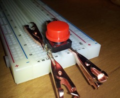 Using the alligator clips, secure one corner on properly. Make sure that the new pin extends as high up on the button’s pin as possible so that we get good contact at least on the top & bottom of the button pin. If there is a curve or loop in the button pin, don’t worry about trying to straighten it. It will not be a problem. That gap will easily fill in with solder. Once you get one of the clips on then do the opposite corner and then the other two pins.
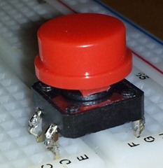 Now that you have everything secure, it’s a simple process of soldering all the pins together. You may accidentally solder your clips to the pins. This is not a problem. A simple touch of the soldering iron will cause it to release without undoing the main solder joint if done quickly. Be careful, the clips can get hot quickly in this process.
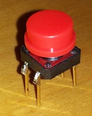 Now you have a button perfect for use in a breadboard that you can depend on to give you a good connection to the rest of your circuit and loosen with use.
 This same technique can be applied to many types of components with similar types of connectors that are not necessarily breadboard friendly.
Enjoy and please share your projects or suggestions in the comments!

