Wednesday, October 28, 2009

U.S. Census Regions

Tonight I was working on a project for my A.I. class I’m taking at MTSU and had a need to have a table of U.S. regions that I could use to join to some other data to allow me to regionalize the data.  I thought that a quick Bing search would have revealed all that I could handle and the problem would be solved.  Well, it turns out that all I could find were all the maps galore but no where could it be found in tabular form.  So, I had to hand enter it based on this info from the U.S. Census Bureau website.  I decided it might be good to post it here for others searching for it and for that time a year from now when I need it again.  It’s totally denormalized for easy use in Excel.  For database work, you’ll probably want to normalize into states, regions, & divisions tables.  Enjoy!

RegionNum Region DivisionNum Division State
1 Northeast 1 New England CT
1 Northeast 1 New England ME
1 Northeast 1 New England MA
1 Northeast 1 New England NH
1 Northeast 1 New England RI
1 Northeast 1 New England VT
1 Northeast 2 Middle Atlantic NJ
1 Northeast 2 Middle Atlantic NY
1 Northeast 2 Middle Atlantic PA
2 Midwest 3 East North Central WI
2 Midwest 3 East North Central MI
2 Midwest 3 East North Central IL
2 Midwest 3 East North Central IN
2 Midwest 3 East North Central OH
2 Midwest 4 West North Central ND
2 Midwest 4 West North Central SD
2 Midwest 4 West North Central NE
2 Midwest 4 West North Central KS
2 Midwest 4 West North Central MN
2 Midwest 4 West North Central IA
2 Midwest 4 West North Central MO
3 South 5 South Atlantic DE
3 South 5 South Atlantic MD
3 South 5 South Atlantic DC
3 South 5 South Atlantic WV
3 South 5 South Atlantic VA
3 South 5 South Atlantic NC
3 South 5 South Atlantic SC
3 South 5 South Atlantic GA
3 South 5 South Atlantic FL
3 South 6 East South Central AL
3 South 6 East South Central KY
3 South 6 East South Central MS
3 South 6 East South Central TN
3 South 7 West South Central AR
3 South 7 West South Central LA
3 South 7 West South Central OK
3 South 7 West South Central TX
4 West 8 Mountain AZ
4 West 8 Mountain CO
4 West 8 Mountain ID
4 West 8 Mountain NM
4 West 8 Mountain MT
4 West 8 Mountain UT
4 West 8 Mountain NV
4 West 8 Mountain WY
4 West 9 Pacific WA
4 West 9 Pacific OR
4 West 9 Pacific CA
4 West 9 Pacific AK
4 West 9 Pacific HI

Tuesday, May 19, 2009

Dare to Dream Different Video Has Been Submitted

Actually, it was submitted last Friday about 5 hours before the deadline…  I’ll make another post later that goes into the details of the project design. 
Damnit Jim!  I’m a programmer not a videographer!

Tuesday, February 17, 2009

Dare to Dream Different Contest Extended

D2DDLogoI just received this email from Marden-Kane, the administrators of the contest.  It now looks like I have an extra month and a half…

Dear Dream Different Contest Semi-Finalist:

Due to unforeseen delays in the delivery of development kits to some Round 2 qualifiers, we are extending the Round 2 entry deadline to help ensure that everyone has enough time to develop their prototype devices.  Round 2 entries are now due no later than 11:59 p.m. PT on May 15, 2009.  It is estimated that Round 3 will start on June 15, 2009 and end on July 31, 2009, but the exact dates will be determined on or around the close of Round 2, based on the availability of selected Finalists to travel to a designated demonstration location. 

For full details, please see the updated Official Rules at http://www.dreamdifferentcontest.com/rules.aspx.
On behalf of the entire Dream Different Contest team at Microsoft and Marden-Kane, we thank you for your patience and understanding.

Thank you very much,

RF

Marden-Kane Inc.

Friday, January 30, 2009

The Goodies Have All Arrived!

I’m a little late in writing this since most of the hardware arrived last Friday, January 23rd, but better now than never…

IMG_8988From Microsoft, I received my development kit for the Dare to Dream Different Challenge.  Included in the kit was the Device Solutions Tahoe-II board with an XBee chip, a USB XBee development board, a one page “Getting Started” pamphlet and a disk with the Tahoe-II SDK on it.  I wasn’t expecting the USB XBee development board and it was a nice surprise since I had already decided on XBee as my communications technology.  I already have an idea on how to utilize this board.

So far, I’ve run several sample programs through the Tahoe-II and am very impressed with how responsive it is and how easy Visual Studio 2008 makes it to develop for this board.  The real challenge it seems at this point is going to be figuring out how to communicate using XBee.  Although the board has support for XBee, I’ve found that the .net Micro Framework 3.0 does not yet have this support.  Fortunately, Michael Schwartz has an open source project on CodePlex that appears to make working with XBee somewhat trivial.  I do wish there was more documentation and sample code available.

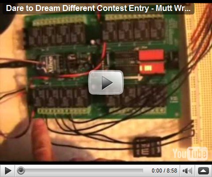
IMG_9001 Since I am also going to need a relay board, I decided on the ZUXPSR1610ProXR 16-channel 10 amp Zigbee (XBee) relay board by National Control Devices.  Since I haven’t figured out exactly what my relay requirements are going to be yet, I went ahead with this one.  It’ll probably have more relays than I need and will certainly handle more current, but I thought that might come in handy after the competition when I decide to use it for other projects.  There is no documentation that came with this board.  However, I presume that switching the relays will basically be the same was communication with the GPIO ports on the Tahoe-II.  I ordered the board with an external antenna since my plan is to eventually house this board in a project box. 

The board operates on a 12V DC power supply which happens to be a big bonus for me since I designed the circuitry for the LEDs on the mock yard to be powered by 12V DC.  The board has a set of terminals where I can run the 12V power off of it.  This is great since it means that I will not have to use two power supplies (one for the board and one for the mock yard).  Something isn’t quite the same as that of the power supply I had been using to build the mock yard with and I’ve discovered that my green LEDs do not shine very brightly when powered from the board.  I’ll have to go back and replace the resistors on the green zone circuit to some with lower resistance.  I’ll do this later on after I have the software working.  As long as the circuit is working well enough for me to tell that the relays are working, I’ll be fine with it for now.

IMG_9008 Speaking of the mock yard…  I put the finishing touches on it earlier this week.  I used some model train supplies I picked up at Hobby Lobby to decorate the foam board with “grass” and a gravel driveway.  Unfortunately, the application of watered down glue used to adhere the “grass” also has caused my foam board to bow up.  This is very frustrating.  I’m thinking that if I spray some water to the bottom side of the board that it may equalize out the shrinkage and cause it to straighten out.  I will also be replacing the bottom piece of foam board with a piece of 1/4” acrylic Plexiglas.  This will allow the circuitry to be easily viewed.  I’ll probably also screw down the sides of the foam board to the Plexiglas to force it to lay flat.  Again, these are all projects that will have to wait until later when everything is functional.  Like the old bird house I found in the garage? :) 

Also, notice that I ran all of the lead wires for the LED circuits to an RJ45 plug mounted on the side of the foam board.  This will make it much easier to separate the parts for transportation when I have to go to Redmond to demonstrate the project for Round 3 ;)  Since I only need three pairs of wires for my three zones and the RJ45 port allows for four pairs, I went ahead and ran a pair of wires under the house that I can use to do some yet undetermined very cool thing with on the house.  Any ideas?

Well, now the real fun has begun.  The task of learning the .net micro Framework and XBee.  Since I don’t really plan to disclose all the details of my development from here out until after the competition is over, I’m not really sure how often updates will continue to be posted here on the blog.  I’m sure there will be some screen shots.  So, stay tuned.

Tuesday, January 20, 2009

Yellow Zone is alive!

IMG_8939Well, I think you get what’s going on here by now.  So, this is the last of the LEDs that have to be wired for the mock yard.  One thing you may notice different about this zone is the little zone within it.  This is going to be a garden area.  In case you don’t know about invisible dog fences, it is possible to create zones like this to keep dogs out of your garden, porch, etc.  This little zone will always be activated when the yellow zone is activated.  The Tahoe-II still hasn’t arrived...  Tomorrow, I’ll start decorating the mock yard and try to make it look like a little more than a piece of foam board with lights.  Must now get some sleep…

Friday, January 16, 2009

The Green Zone is Alive

The electronic parts I ordered for the IMG_8846model yard arrived early, so it was time to start soldering again.  Tonight I got all of the green LEDs in place and wired up.  This is a much more tedious task than you would think from looking at the end results.  I also finished up the last section of the red zone.

I’m taking a little time off and heading to Savage Gulf for three days of backpacking with Jr. this weekend.  So, I guess it’ll be Monday night before I can finish up the yellow zone.  If we don’t freeze to death (my thermometer says its 8.8° F right now…) then there should be a trip report here after I get back.

With any luck maybe the Tahoe-II will arrive early next week.

Thursday, January 15, 2009

Red Zone is complete…almost.

For the Dare to Dream Different Challenge, I have decided to begin by building a mock yard that will have three different “zones” that will be controlled by the Tahoe-II board and my .net Micro Framework software.  There will be three zones in this yard: red, green, and yellow.  Each zone will be a series of LEDs that will light when that zone is activated by the software.  Since I already had a supply of red LEDs, I decided to start there while I wait on all the other parts to arrive.

Red Zone is Alive!
The Red Zone is alive!

You may note that the red zone isn’t completely alive…  I was one LED short, so the last section isn’t lit yet.  This will be remedied as soon as the rest of the parts arrive.

IMG_8809

The yard is constructed of a piece of foam board that has been cut so that it folds in half.  The circuitry is sandwiched between the two pieces for its protection.  Each zone will be a separate circuit and they will all terminate at an RJ45 jack for easy connection to the relay board and Tahoe-II.  Everything is powered by a single 12V power supply recycled from an old Linksys router.

Next, I’ll finish up the other two circuits and maybe add a little decoration to polish it off.  Hopefully, I can get all this done before the Tahoe-II arrives and I’ll be able to then focus entirely on the real work at that point.